First attempt at a 6DoF robot arm
When news of Covid-19 broke, I was cautiously optimistic that the virus would be less transmissible. Within a couple weeks however, I realized that we were in it for the long haul. I decided it was time to take advantage of an unprecedented amount of free time.
My 3D-Printed 6DoF Arm Journey
My first design iteration did not have many things going for it to say the absolute least.
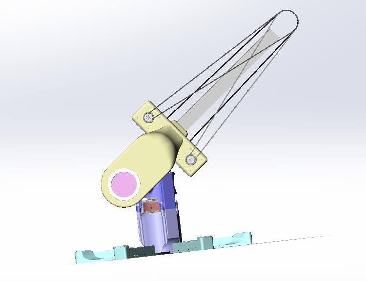
Perhaps overly ambitious, I had taken heavy inspiration from the team over at Haddington Dynamics:
I liked their design philosophy regarding weight distribution, placing heavy components such as stepper motors and gearboxes closer to the base, and using timing belts to transmit that power to the rest of the joints and end-effectors. If there was one thing I could take away from all of my time in high-school robotics, it would be: keep end effectors as light as you can get away with. So this setup seemed like a no-brainer.
It didn’t take long for me to realize I had downplayed severely many of the the most obvious downsides that came with opting for such a setup.
Firstly:
I had opted to use NEMA17 stepper motors. Besides the fact that the Haddington Dynamics guys did too, I decided to use NEMA17s because they were reasonably light, reasonably powerful, and my past robotics experience didn’t include very many stepper motors, but instead DC brushed and brushless motors. I wanted some of my own experience with them.
NEMA17s aren’t very strong. This meant that a gearbox was required to increase the mechanical advantage produced by the motors if my arm had any hopes of lifting itself. For this, the Dexter guys used the engineering marvel that is the harmonic flex-spline gearbox, featuring zero backlash, a surprising degree of back-driveability, however they are also mind-numbingly expensive to get a hold of due to obvious reasons.
Which sadly left me to my own devices…
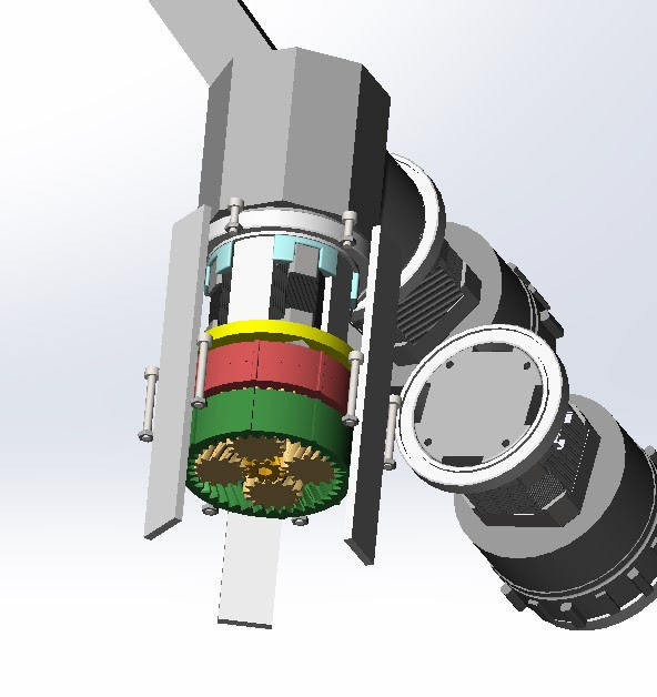
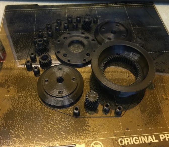
I spent many days and late-nights trying to fine-tune parameters of my 3D-printed planetary gearbox (you read that right… never again) to have minimal backlash with minimal friction. At the end of the day, I was never going to get very good results in either of these aspects since the accuracy of my printed parts is only as good as the accuracy of my printer. My reduction ratio was also decently high at 38.4:1. With the amount of friction in my 3D-printed gearboxes, the ability to back-drive my motors was simply out of the question.
Secondly:
Unsurprisingly, sourcing niche parts like >1000mm loop timing belts is a difficult endeavour. I don’t have a home machine shop, and sourcing pre-cut custom-length 1”x1” square tubing proved impossible. The Dexter guys used a MarkForged industrial 3D-printer for the printed parts and even had carbon-fiber reinforced structural parts printed from it. I was sitting here with my meek and humble (but able) Prusa Mk3S 3D-printer.
For these reasons, along with many other concerns I had about how the design was progressing, I made the executive decision to scrap this iteration.
Back to the Basics
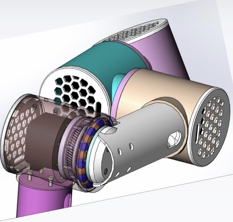
I determined that my best course of action was to reject modernity and return to tradition with the proven line of UR style arms from Universal Robots.
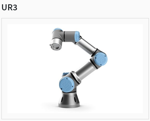
This style of arm featured actuators situated directly at each joint within the arm, massively simplifying the design constraints.
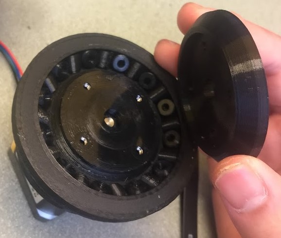
I further iterated on my gearbox design, implementing finer gear teeth, allowing me to create larger reduction ratios and a more compact gearbox system. Now that the actuators were situated directly at the joints, I had to increase the diameter of the joint bases to help the design handle the increased radial and axial load. I was really interested in using thin-section bearings, but once again ran into some trouble. So in typical fashion, I tried my hand at designing a custom slewing bearing using printed cylindrical bearing beads (you’ll find 3D-printing spheres to be quite difficult). This first iteration of the gearbox features a swept-cut side surface, which didn’t make it onto the final iteration. This is one of my prouder creations.
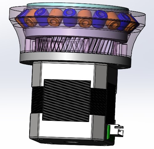
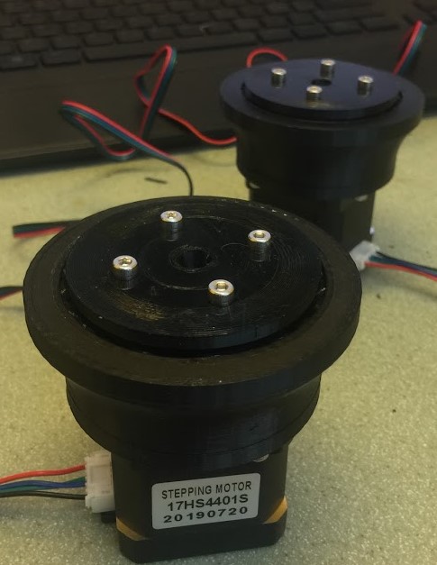
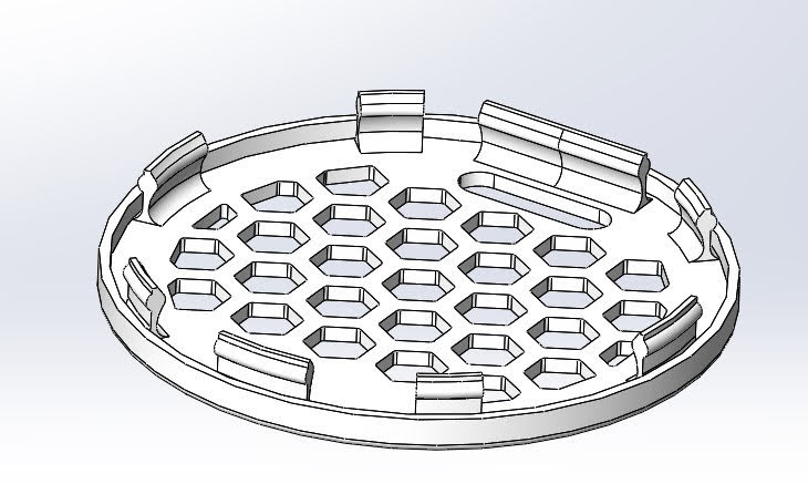
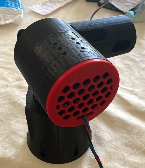
After much time, I had finished the arm - and added hexagonal pocket patterns to the motor port covers for extra flair.

Now that I have the thing built, I want to start making the thing move. I used an Arduino Mega 2560 and a Ramps 1.4 shield with A9488 Drivers and uploaded a simple Step+Direction control sketch.
That was easy enough. Now how about making it move predictably? I then went onto the web to search for ways that I could coordinate stepper movement effectively, and found much more than I was expecting.
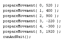
This video by iforce2d had everything I was looking for and more. By the end, he had introduced a simple sketch that would allow you to prepare stepper movements for multiple steppers and execute them, complete with stepper start-time end-time coordination, linear speed ramping, and even interrupts. This massively simplifies everything. And this is where that got us:
Next, I needed to figure out how to provide angle inputs, and I also wanted to move out of the Arduino IDE interface, since preparing movements within the sketch currently consists of editing the motor ID and step# parameter manually:
I had to create my own serial command protocol that my Python code could send, which the Arduino could then receive and interpret. My protocol needed to be able to assign a Motor ID as well as step count for that particular motor, and I also needed a protocol for executing the runAndWait() function. So I ended up with the following command structure:
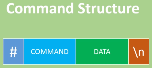
To control the parameters for my prepareMovement() method in the Arduino sketch, my Command prefix would consist of MTR0, MTR1, … to MTR5 to pass in the Motor ID, and the Data suffix would pass in the desired step count. A full command would look something like #MTR2500\n to prepare movement on motor 2 for 500 steps, or #MTR51780\n to prepare movement on motor 5 for 1780 steps. For the runAndWait() method, a simple #EXEC\n command would be sufficient.
The Kinematics
Forward and inverse kinematics let you convert between the joint angle space (theta1, theta2, theta3, …) and the cartesian coordinate space (x,y,z,p,r,y) relative to the grounded base frame origin, or vice versa.
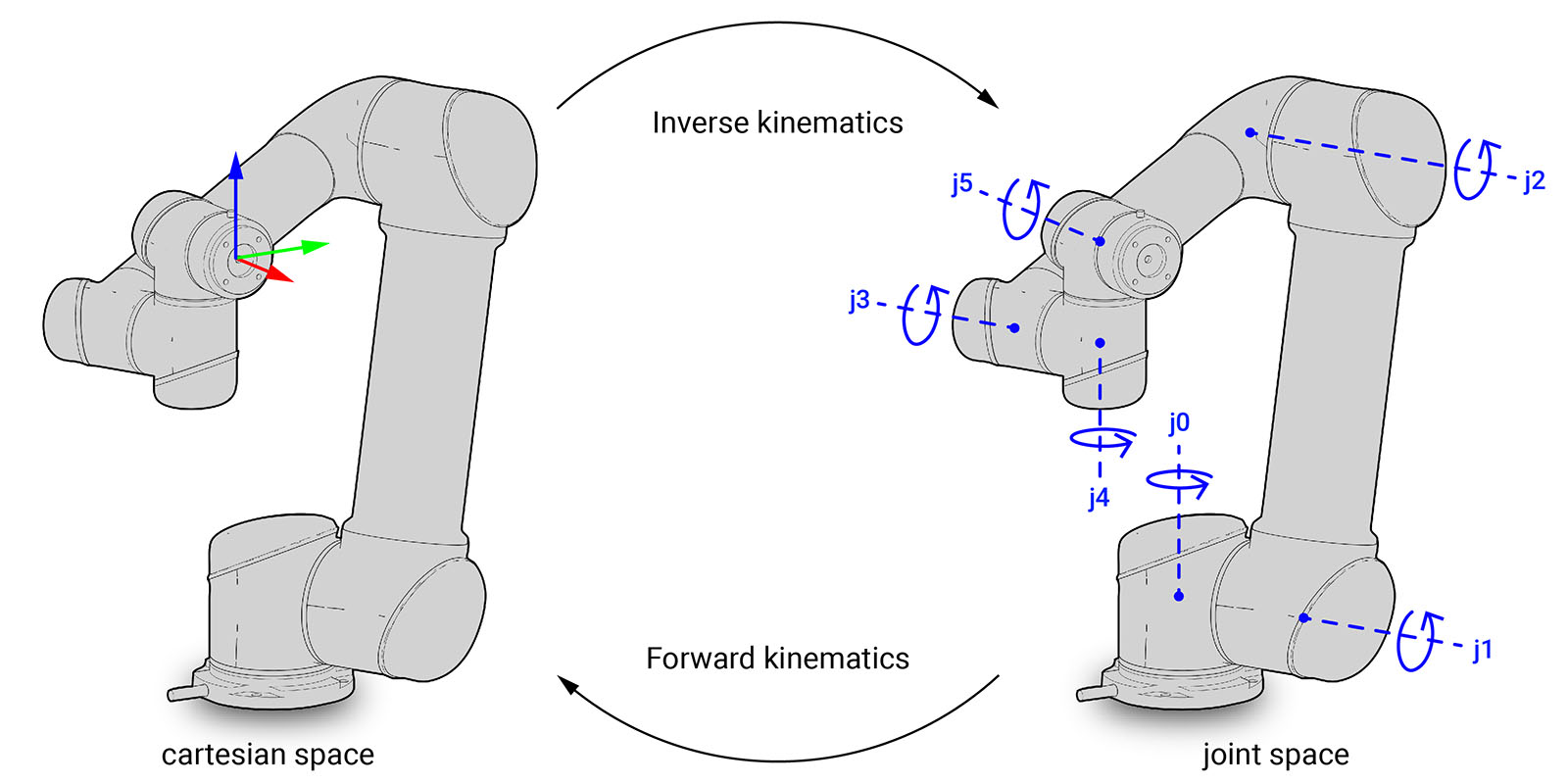
This allows us to determine a robot’s kinematic chain, such as a robot manipulator or animation character’s skeleton, in a given position and orientation relative to the start of the chain, and is necessary for pretty much all things involving robotic linkages.
Figuring out the Forward Kinematics for my arm is laid out in one of my previous posts and can be found here, so I won’t go into much detail for it here. In short, the forward kinematics is pretty simple, defining the full kinematic chain as a product of several SE(3) transform matricies while using joint angles as input values.
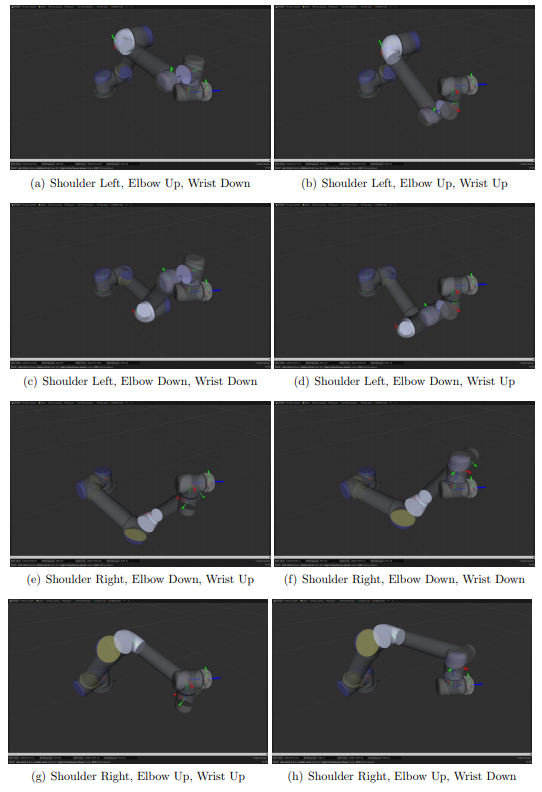
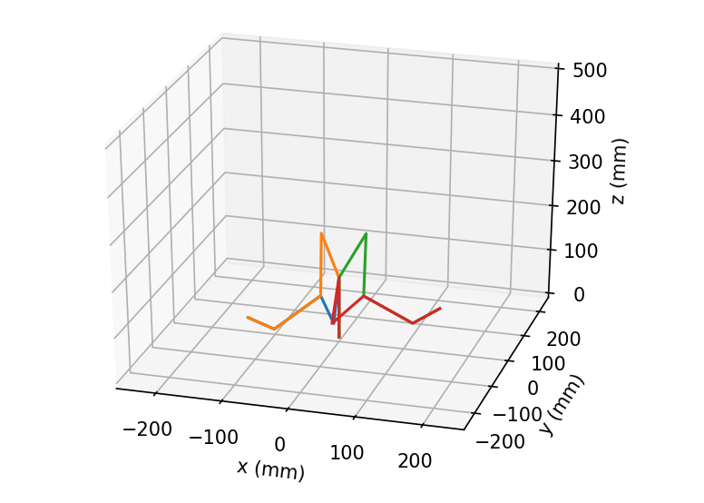
The Inverse Kinematics (IK) process is the inverse of the above, and is more involved. IK must provide joint angles from the desired pose in cartesian space. One reason why this is more complicated is because depending on the kinematic structure, the IK solution may not be unique. In the case of my arm, for every unique cartesian space input, the IK result can consist of multiple joint space solutions:
Some of the resources I used for 6-revolute joint IK are cited below123. Going through the pertinent literature was time consuming, taking roughly 2 weeks in total.
The next step is about as involved as parsing the literature: translating useful information to develop my own IK model implementation. I would frequently end up in what were seemingly dead ends, and there were also points where I knew I was close but couldn’t pinpoint what was causing issues:
Eventually, I would come across some stray negatives, undotted i’s and uncrossed t’s scattered around my implementation, and I eventually got there.

It’s not easy to see, but all of the 8 possible configurations converge onto one end-effector position!
And it All Comes Together
Now that we have our very rudimentary motion planner implemented, a user interface, and our FK and IK models verified, it’s time to stick it all together with some scotch tape and bubblegum.
A postmortem discussion: there are several areas that I could improve upon in future iterations. First off, you might’ve noticed that my interface was lacking a homing procedure button. This particular robot is completely open-loop, relying only on the accuracy (or lack thereof) of the steppers. The stepper gearboxes were also not back-driveable, so going entirely open-loop was less of a risk. There’s a lot to be desired from the structural rigidity of the whole thing (after all, it’s entirely structurally fabricated from 3D-printed PLA filament). For what I set out to do (to learn) I think I did a pretty good job, though, I would consider the current iteration to be unoptimized for practical usage :(
In the future, closed loop control and improving arm structure rigidity is definitely top priority.