Elevated Robotic Assistive Device
Team : Adham Elarabawy, Justin Yu
Robotic systems have been developed and utilized primarily for enhancing productivity and safety in various industrial and agricultural settings, such as manufacturing assembly lines, warehouse operations, and crop harvesting. In contrast, robotic devices in personal and domestic markets have been largely limited to toys, drones, and cleaning devices, occupying space on the ground or in the air. While floor-based mobile robots like telepresence robots have potential for automating processes and assisting people, their need to navigate around obstacles, including people, furniture, stairs, and pets, can make them expensive and intrusive. Therefore, elevated robotic systems with unique mechanical designs and control mechanisms that traverse along elevated tracks offer significant advantages.
Elevated Robotic Module Chassis Mechanical Design
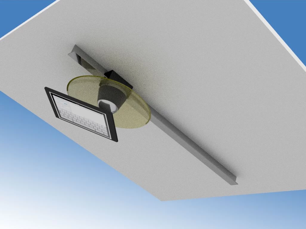
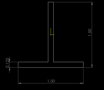
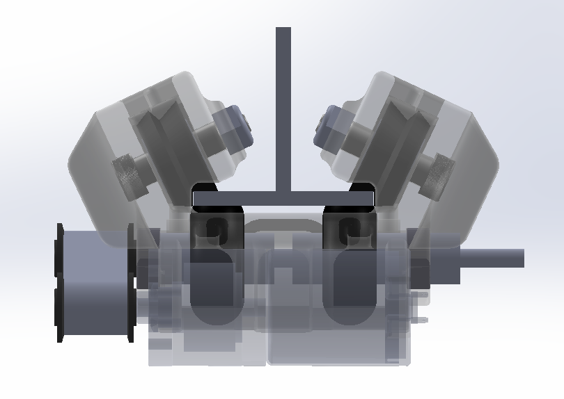
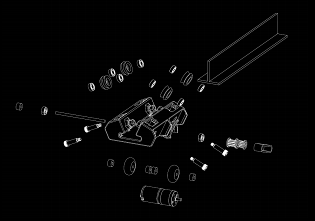
In an exemplary embodiment, an elevated robotic module traverses along a T-extrusion track as shown in the following figure.
The rigidity of the base carriage’s mounting solution to the track improves stability and efficient traversal. Previous carriage iterations used grip wheels or 3D-printed tread wheels, but vertically oriented wheels provided consistent contact during motion and were most effective.
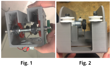
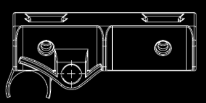
Some vertical-wheel designs utilized lips on the treads to lock the carriage laterally (Fig. 1). For horizontally oriented wheels, lips are added to secure the carriage in the vertical orientation (Fig. 2).
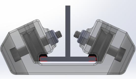
The lip-wheel designs were not ideal as pressure on the lip faces increased the friction, making it difficult to achieve tight and secure contact with the track. There was always play between the lip faces and the extrusion faces, causing the carriage to shift around while the track remained static. In an exemplary embodiment, angled groove wheels are used to create significant contact with the top corner edges of the track, bypassing the friction issue entirely.
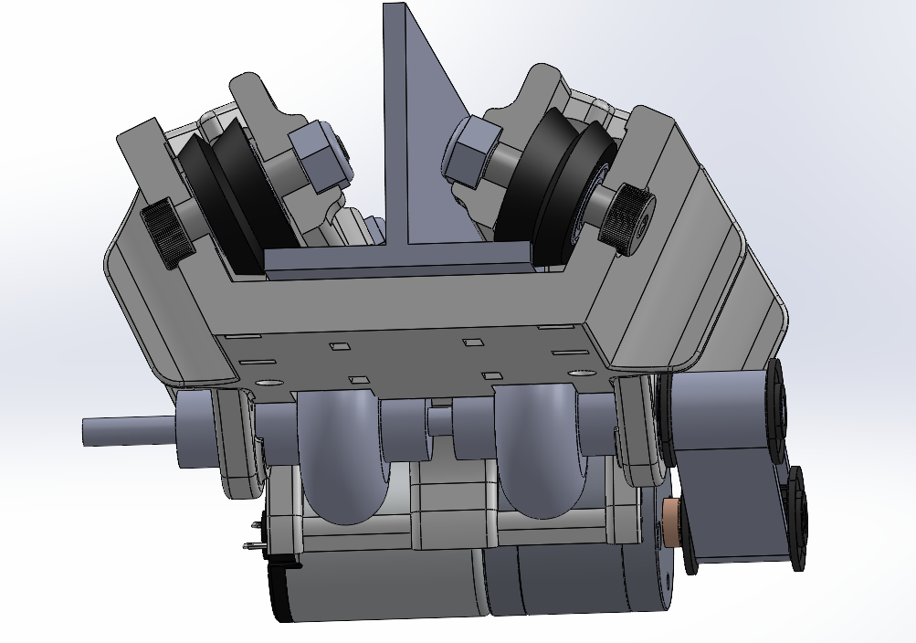
The use of angled groove wheels creates two rolling surfaces, one on the top and one on the side, without producing excessive kinetic friction. This design allows both tread surfaces to “peel away” from the track faces, resulting in a thinner contact patch than with lipped designs. To further secure contact, the grip wheels that drive the carriage from the underside are placed close to the 3D-printed groove wheels, minimizing bowing and deflection. 45 degree metal v-groove bearings are a robust option for mounting the v-groove wheels.
In order to support larger loads on the base carriage without causing excessive torsional stress, a steeper angle than 45 degrees may be necessary. For instance, an exemplary embodiment might use a 65 degree angle from horizontal, which provides improved mounting support in the vertical orientation while still allowing for a thin contact patch on the side wheel contacts.
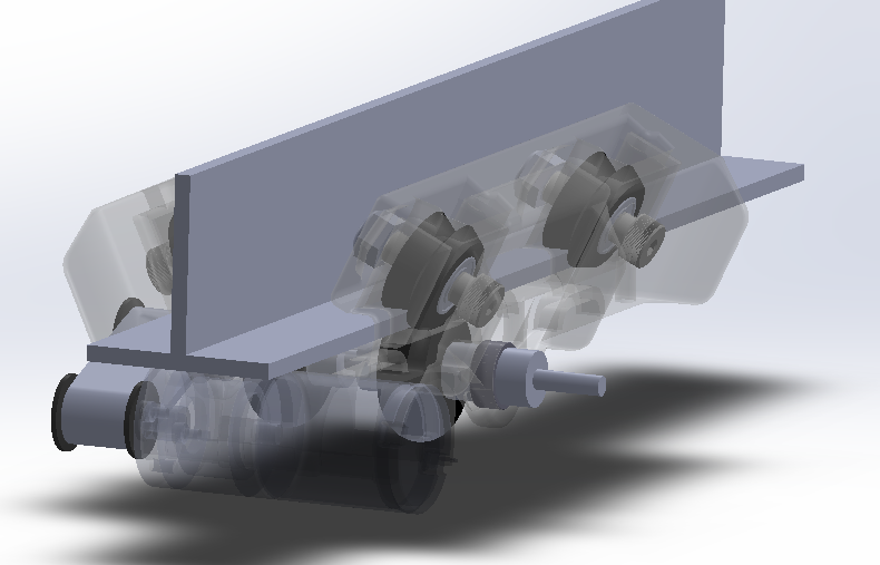
In an exemplary embodiment a compression of 0.03 inches provided to the grip wheels on the underside provides a secure contact between all wheels and the track. Care must be taken to ensure the carriage isn’t too tight on the track which would prohibit the motor from overcoming friction such that it can begin to turn the wheels.
Vertical wings or tabs may be added to the side of the carriage to increase the effective thickness of the base, alleviating some of the torsional stress from the load of an additional module. Increased effective thickness works for the same reason that tape measures use curved profiles to allow them to remain extended at distance, despite being made of such thin material.
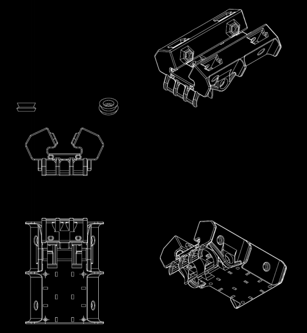
In an exemplary embodiment, shoulder bolts may be used to retain a 3d printed wheel+bearing combo rather than regular bolts due to its smooth surface, allowing for better fit of the bearing inside races compared to bolts with thread all along its body.
Elevated Robotic Module System Control
An exemplary control mechanism is comprised of a SISO (single input single output) system–input is the voltage applied to the motor and the output is the linear position of the module on the track. This highly controlled and model-able environment allows the elevated robotics module to act as a very potent platform for a wide application of different technologies. However, the versatility of the elevated robotics module platform necessitates proper systems design in order to allow it to be easily applied from one application to another.
An exemplary system control and pipeline of the elevated robotics control system is shown as follows.
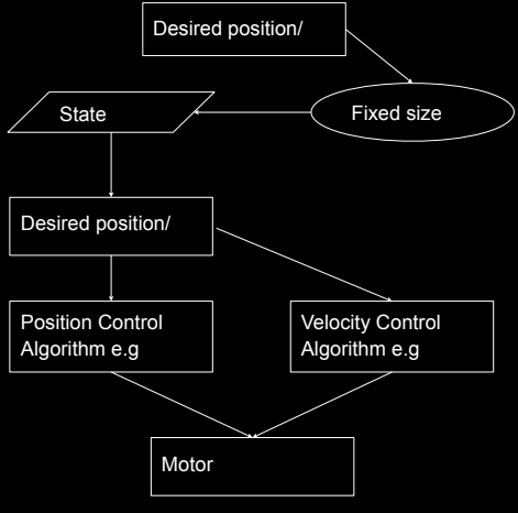
As aforementioned, keeping the low-level control of the elevated robotics module consistent is extremely important because it allows full utilization of the ERAD platform’s versatility across multiple platforms. A summary of the pipeline follows: The state vector that fully defines the elevated robotics module is its position (in meters) and velocity (in m/s). In an exemplary embodiment the drive signal would then be the desired position/velocity, meaning that the low-level elevated robotics module control would have to handle getting the module to those desired setpoints with only the drive signal as input. In this way, no matter the application that the elevated robotics module is deployed in, the high-level code only ever has to tell the module the desired position/velocity setpoint, and the position/velocity control algorithms will take care of reaching the setpoints.
However, considering the complexity of the more advanced applications an improved buffer system to handle the latency between the sent setpoints and the module actually reaching those setpoints is desired, for example, as a hand-gesture-obeying robot. In the example, the length of a hand swipe would determine how long the module would go in the direction of the hand swipe. For example, long swipe to the right would indicate a 30 cm movement in the right direction, and a short swipe would indicate a 10 cm movement. A computer vision system could read multiple hand swipes before the elevated robotics module could actually reach the desired positions based on the last setpoints. Instead of overriding the past commands, a sequential order of the hand swipes is retained.
Using a simple list or dynamic buffer is not memory efficient when resized or when their elements are rearranged/manipulated. Instead a Fixed-Size FIFO (first in first out) ring buffer is used. The explicit advantages of this approach are many:
First-in First-out behavior gives a temporal priority to the newer commands. In the case that all of the slots in the buffer are used, old commands are popped out of the buffer before newer commands The fixed size of the ring buffer allows better management processing constraints (namely memory), which is especially important when running an object detection pipeline for hand tracking and gesture recognition on the same platform. The size of the FIFO ring buffer can be reduced as a compromise on how many back-logged commands we can run sequentially, for the sake of the object detection pipeline. This allows the ability to compromise on ignoring entire commands instead of the individual resolution of each command, which is very important, because missing new hand gestures or receiving sporadic hand detections due to insufficient system capabilities limits the performance of the system. In this case resizing the ring buffer is not needed, making it very memory efficient.
The existence of a ring buffer allows multiple processes to cleanly control the elevated robotics module without interference between them. For instance, the hand gesture recognition pipeline can add a drive signal to the ring buffer, and then some other process (like a direct drive command) can also add to the ring buffer, and they will get executed sequentially, retaining the drive signal sent by both processes.
It should be noted that the StateTracker Node in the diagram is a purely heuristic layer that allows setting a priority to some processes in terms of executing a drive signal. In a deployment scenario, it is likely that the StateTracker layer gets shifted up to a higher abstraction level before the drive signal gets added to the FIFO ring buffer, but it is convenient to have an abstracted layer for final heuristic logic in between the ring buffer and the actual execution of the drive signals. This layer is also responsible for determining when the position of the elevated robotics module has plateaued/converged on the setpoint, which is when this layer triggers the next drive signal in the ring buffer. This is unique from other control law implementations in that the system doesn’t try to reach the setpoint indefinitely. Rather, a tolerance for the position delta is defined from the setpoint and whenever inside that tolerance, the position is assumed to have plateaued. In an exemplary embodiment the elevated robotics module position is marked as plateaued within tolerance for more than 5 iterations of the main While loop, then the next drive signal in the ring buffer is executed.
The Position/Velocity Control algorithms are the common Feedforward + PID Feedback approach to controlling a motor’s angular position and angular velocity. The control algorithm effectively drives the elevated robotics module towards the desired drive signal position at the designated velocity setpoint. The velocity setpoint is reached by effectively adding a default negative term (proportional to the difference between the desired velocity and the current velocity) to the common FF+PID control law for position control.